A few weeks ago, somewhere around late November, I drove across the Netherlands to pick up a Durst Laborator 1200. It was listed as incomplete on Marktplaats, I offered €100, and was allowed to go pick it up in ‘s-Heerenberg. It’s quite a drive from Amersfoort, but I rarely decline an opportunity to go towards the German border as it also gives me an excuse to visit a Getränkemarkt and pick up a case of my favourite beer, Köstritzer.
Arriving in ‘s-Heerenberg I was greeted by the seller: a woman, hard at work in an art studio, apparently her dad’s, who passed away. She told me she found the enlarger in the attic while cleaning up for sale, among some of her dad’s other art stuff. I went up to take a look and, to my surprise, saw a giant 1m70 tall monster on the floor of a type I’ve never seen before:
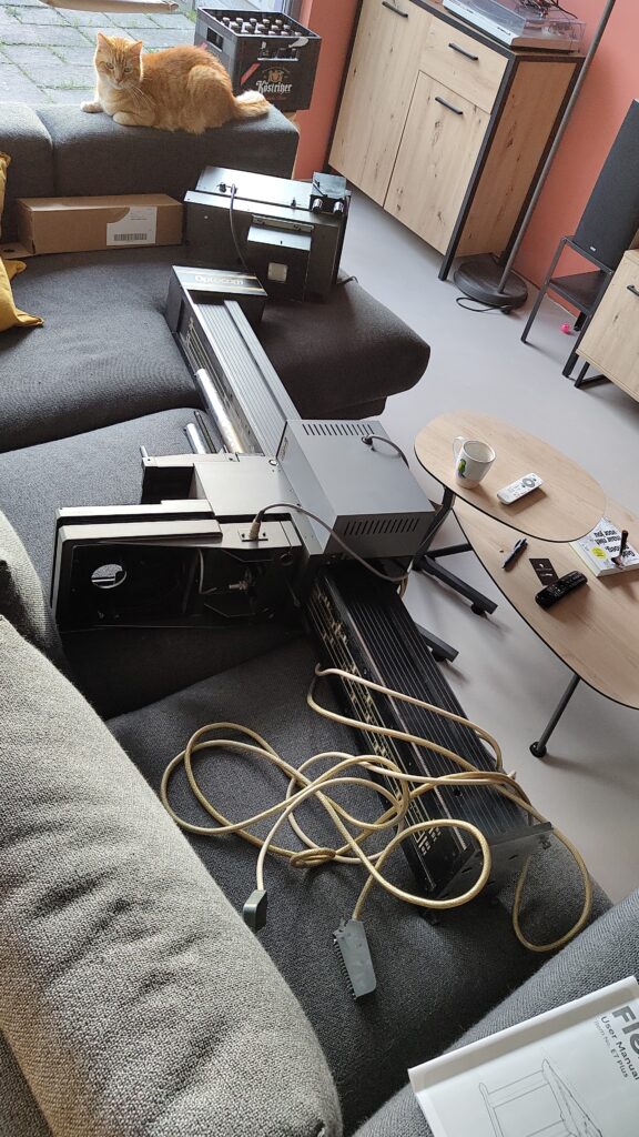
This is a Durst Optocom from the late 80’s in the Colikit 1201 configuration, meaning it’s equipped with a CLS501 color head. Quite a hefty beast at 50kg, which I found out the hard way together with the seller, having to lug it down 2 sets of steep cramped stairs. As mentioned before, the column is 170cm high, with the total enlarger taking up 2 meters from baseboard to maximum extension of the head. The CLS501 has a “Laborator 1200” label, which might explain the confusion regarding model type. “Optocom” is printed on the protective box around the counterweight springs. It also comes with an Optotris revolving lens stage, in which you can screw 3 enlarger lenses to switch between.
My copy is missing the Femoneg negative carrier, and only comes with the Femobox 35 diffuser for 35mm film. Both are sourceable, though. But the biggest challenge, aside from the fact that everything smells like 40 years of cigarette smoke, is the fact that it’s missing the original Opto-ecu controller box, meaning it’s unusable in its current state.
I sent a mail to Jeroen, the guy who runs Qoppa Photografica, inquiring about the missing pieces. He replied with a list of replacement parts (awesome), but also with some pictures of the Opto-ecu controller that he happened to have lying around!
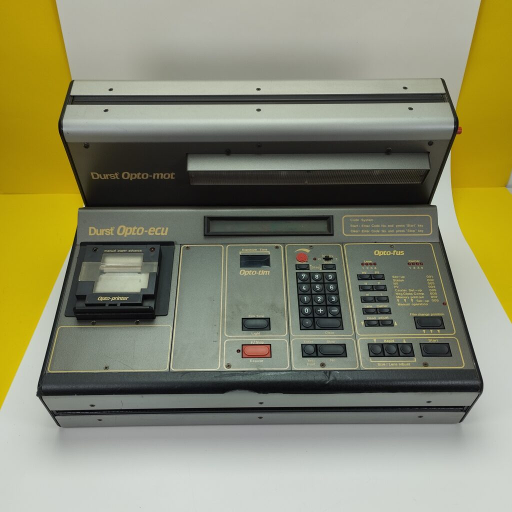
Yeah, that’s a bit too large for my tastes. The Opto-printer part can be used to print a “receipt” of sorts which lists the parameters used to make your current enlargement: lens used, distance to baseboard, that kind of stuff. Opto-tim is the timer part, and Opto-fus is an autofocus system.
After some more digging I managed to find the manual, of which I will attach a copy here. From this, and from some service manuals I found on this great website, I could determine the controller is probably Z80-based. Which was pretty much the norm in the 80’s, of course. Nothing more to find online, so let’s open it up!
Unscrewing the motor shroud (just a couple of screws that hold it in place) revealed a 24VDC motor with gearbox, a 12V encoder (Tekel TK163, 100 pulses/rotation), a load of wires and a PCB. After some sleuthing I found out the head had its own 24VDC motor and encoder (Elap EB40). The Optotris lens turret has 3 NO switches which are used to indicate which lens is currently in position.
Both the column and head have their own top and bottom limit switches.
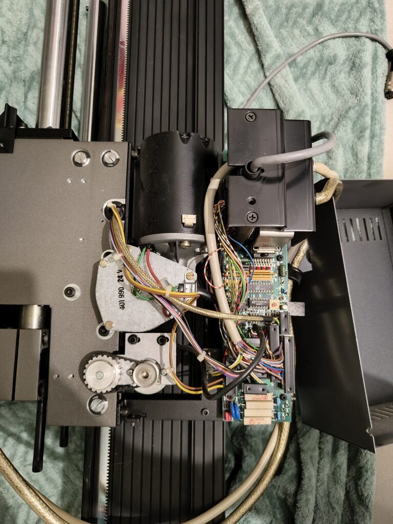
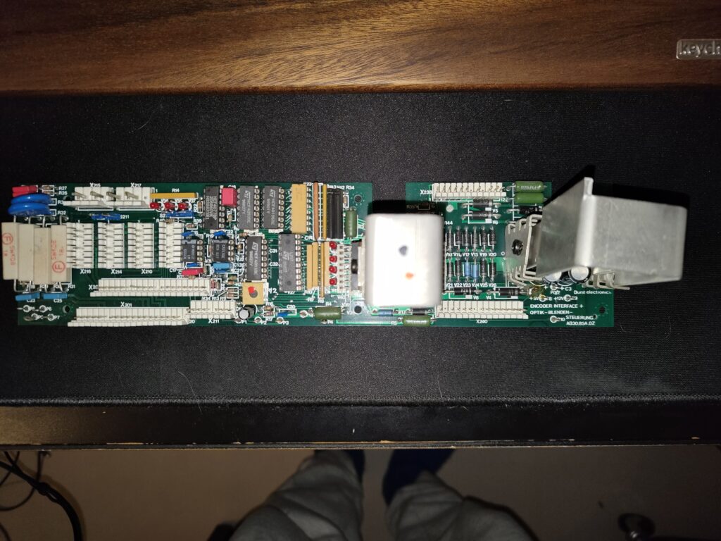
The PCB looks complicated, but it’s deceptively simple. It’s mainly a stack of analog logic:
– a HCF40106BE hex Schmitt trigger
– a HCF4096BE J-K type trigger
– a HEF4077BP quad XNOR gate
– a CA3130E opamp
– a 555 timer
– 2 old-style L298 motor controllers (left heatsink)
– 7812 and 7805 LDO’s for encoders (12v) and 5V TTL parts
– a load of rectifying, snubbing and shaping passives
Most of it is ST-branded, so I’d say about 90% of the components on this PCB are actually made in Europe!
The PCB has several connectors:
– X210, Optotris turret position switches (3 pieces)
– X211, head position encoder
– X212, column position encoder
– X214, top/bottom limit switches for head
– X216, top/bottom limit switches for column
I reckon this oldschool style analog logic is mainly used for signal conditioning, to transport all required signals from and to the main control box, which does all the heavy lifting on its Z80 as the enlarger itself has no microcontroller. The PCB has 2 connectors leading to a larger 26-pin (X238 + X200) and a smaller 12-pin (X201 + earth) DIN cable, one for motor control and one for encoders, according to the manual. Position X240 is empty.
The combination of lens selection switches and encoders means this monster can actually perform motorized autofocus! I’ll dedicate a post to the mechanics after writing out the workings of the new PCB + software.
Rebuilding this entire analog logic chain seems like a disaster waiting to happen, so the logical conclusion is of course to design a completely new control PCB! In the followup post I’ll write out the details of how I designed the new PCB, some more details about the electrical configuration of all the parts and the design choices I made because of this. Sneak peek: it’s all going to be RS485, and not one, but 2 micro’s! Gotta prove that embedded systems education wasn’t for nothing 😉
1 thought on “Optocom – part 1”